MLX90614 Distance to Spot Ratio
Disclosure: Some of the links below are affiliate links and we only earn a small commission if you purchase through our links at no additional cost to you. The earning mainly used for maintaining the website.
In the previous tutorial – MLX90614 Distance Dependency, I show you how the temperature graph behaves at a different distance away from the MLX90614. So basically a lens hood or Fresnel lens can increase the range of detection without much affecting the temperature readings. But this does not mean you can measure an object’s temperature very far.
You may notice that the temperature readings vary with the distance away from the MLX90614. Even at 30cm, the sensor is still able to read my hand temperature. However, the temperature readings are not making any sense. So, technically there is a thing, called distance to spot ratio.
Starter Pack
- Arduino Uno/Mega/Nano
- MLX90614 Contactless Infrared Temperature Sensor
- Copper Lens Hood
- Breadboard
- Jumper Wires
Distance to Spot Ratio IR Thermometer
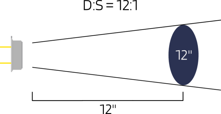
We often hear the term “Distance to Spot Ratio” in contactless infrared thermometers. The distance to spot ratio (D:S) is the ratio of the distance between the sensor and the target to the size of that target being measured. Let’s say a D:S ratio of 12:1, a 1” diameter size object can be measured at a distance of 12”. If the D:S ratio is low, the target object has to be closed enough to the sensor for a more accurate reading. In a situation where a high-temperature object, a higher D:S ratio is preferred as safety is concerned.

The temperature readings may not be accurate if the object is placed at a distance out of the D:S ratio. The distance should be at most exactly or smaller than the D:S ratio. From the testing I did in previous tutorials, within a certain distance, the temperature readings are quite good. After some distance away from the sensor, the temperature readings start dropping. This is because the object size is not completely filled the field of view (FOV) of the sensor. The sensor detects all the infrared radiation in the FOV and returns an average temperature at the area of that spot.

Distance to Spot Ratio Calculation
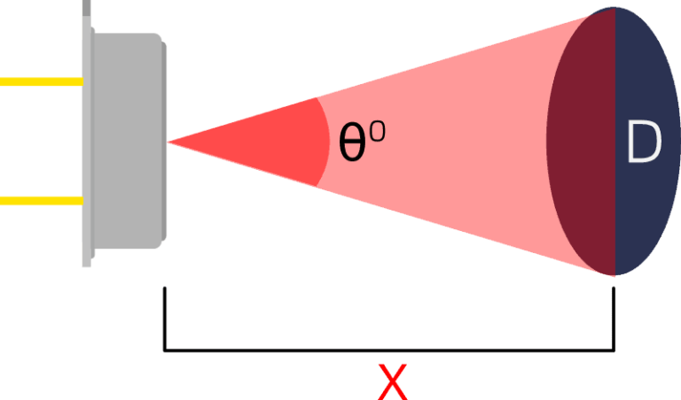
It is important to know the distance and the size of the object to be measured to get a more accurate temperature reading. A simple mathematics formula, trigonometry, can use to calculate the distance to spot ratio.

Cutting the triangle into half, we get a right-angled triangle. We use a tangent formula to get the distance “X”. This is the maximum distance where the object should be placed to get the temperature close to the object.

Bare MLX90614 Distance to Spot Ratio
In order to get the distance to spot ratio, we need the field of view of the sensor. The MLX90614, model “BAA”, the FOV is 90 degrees. By assuming a 1” diameter size object, insert all the values into the formula derived to get the distance to spot ratio of this MLX90614.

From the formula, we get the D:S is 0.5:1. This is definitely a short distance to spot ratio. With a roughly 6cm diameter size hand of mine, we multiple the D:S 6 and get 3.0:6 in cm. This means that the maximum distance to read 6cm diameter area of my hand is 3cm from the sensor.

Copper Lens Hood Distance to Spot Ratio

I have made a copper lens hood to compensate for the PLA material lens hood in the previous tutorial. If you remember, the PLA material lens hood could not read my hand temperature at all. Due to the copper’s high thermal conductivity properties, it should show a better result.
Overall the temperature behavior looks much better compared to the PLA material lens hood. As can see, the temperature readings are quite good when near the sensor. But up to a certain distance, the temperature readings start to show a decreasing trend as I move away from the sensor. At 30cm, with the copper lens hood, is still able to catch my hand temperature. But, as I mentioned, the temperature readings are not making any sense.

We need to find out the distance to spot ratio of this copper lens hood to get a more accurate temperature reading. With the 60 degrees FOV of the copper lens hood and 6cm diameter of my hand size, we get roughly 5.2:6 in cm.
The Testing Result
So, with all the theories and calculations, let’s go for real testing. The testing was conducted with a distance up to 6cm. Starting from zero cm, then increase by 1cm up to 6cm at an interval of 10 seconds. From 6cm I stayed for 20 seconds then back to 5cm for another 20 seconds just to make the serial plotter graph more obvious.
Alright. From the testing result, within 3cm, the bare sensor shows quite stable temperature readings. At 4cm, the temperature readings start to drop slightly. It shows a decreasing trend after that. The distance to measure my hand size, 6cm is the same as the distance to spot ratio calculated earlier. For the copper lens hood, the result is unexpectedly good. As the calculated distance to spot ratio, the maximum distance to measure 6cm diameter is roughly 5.2cm. But in the testing, up to 6cm still shows stable temperature readings. I did not go any further as the testing is controlled at 6cm.
Nay! We Love Videos
Bye Bye
Well, the sensor without any lenses can measure distance maximum up to 3cm. With the copper lens hood of 60 degrees FOV, the range increased to 6cm, which is almost double. If you wish to further increase the distance of measurement, a smaller field of view, FOV is definitely a must.
Hope you find this tutorial helpful in your projects. Subscribe to our newsletter for more tutorials.


Very nice information
Thanks
Hello
I have an infrared MLX90614-BAA module and I want to increase its distance.
Please send me the dimensions of the copper hood so that I can make it.
Thanks
Hi, I have uploaded the STEP file into my GrabCAD,
https://grabcad.com/library/copper-lens-hood-1